How should I bypass this power switch?

This old machine did not turn on a few weeks ago. I don't even need it for much these days, but want to grab whatever is still of value on the HDD's. I already tried multiple outlets and cords, so that isn't the problem. When I hit the front power switch absolutely nothing happens, and a couple of times that switch has felt "wrong". I'm thinking either the PSU is gone, or the front power switch is faulty.

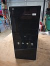
One photo shows the front of the case, and who ever designed it had a desire to see lots of useless blinking blue lights. Of the four white "buttons", the only real button is the power switch on the right end. The left end says reset but doesn't depress, while the two in the middle just blink away for reasons unknown.

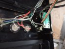
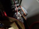
The other photo is of the inside of the front panel, where again, the power switch is on the right end. There are 2 leads for power, and 2 leads for the LED, and I'm not sure which are which. It isn't even necessarily true that the wires closest together are common to either the power switch or the LED. I want to bypass this switch and just use the PSU switch to first test if the PSU will fire up at all.

So, if I cut all four wires, plug in the machine, turn on the I/O at the PSU, and then contact the black wire against the white wires (one at a time), and then do this again with the green wire, will this confirm the PSU is shot?
 

Attachments

  • Asus Front.jpg
    Asus Front.jpg
    209 KB · Views: 10
  • Asus Panel.jpg
    Asus Panel.jpg
    244.8 KB · Views: 11

hardware is not my greatest forte, but does the above link help with differentiating the wires?
when my power button when out before, I just replaced the whole button, many years ago, :)
 
This old machine did not turn on a few weeks ago. . .
Your second picture would suggest that in the past someone already tampered with those two switches (power and reset), and not even in the most professional way (blobs of epoxy glue instead of neat heat shrink tubing), thus I'd rather avoid making the situation even worse.

I'd rather follow the wires from the power switch (there should be only 2 of them but for some reason you have 4) to the motherboard connector - it should look like an array of gold-plated pins 1/10" spaced from each other, protruding from the board.
Once there I'd check the captions on the board near the pins: one of them should read "PWR" or something like that, another one should read "GND" - usually they are contiguous.
Then I'd plug in the PC and with a tiny screwdriver I'd shortcircuit pin "PWR" to pin "GND" for a second or so, and see what happens. If the PSU and the motherboard are OK the PC should show signs of life - fans spinning, LEDs blinking, beeper beeping and so on.

Should you run into any problems or uncertainties doing that, please write back - I'll check XPForums regularly to see if I can be of any help.
Except at 12:00 pm (CET), when I'll be toasting the incoming 2025 and possibly firing a few pounds of exploding material :)

By the way...

:):):) HAPPY NEW YEAR to everybody! :):) :)
 
Last edited:
I'd shortcircuit pin "PWR" to pin "GND" for a second or so, and see what happens.

Good idea Chiron, except for how much disassembly would be required first to access the front panel pins. LOL

This machine has an Asus MB, and when I took the side of the case off and stuck my little flashlight in there it appears that there is only one long plug that fits to all the panel pins. I would need to remove HDD's and possibly more to even get to it. But now that you mentioned tracing the wires back to the MB, I can take a 2nd look and confirm the wire colors by referencing the MB Manual. Then I can short that connection by just cutting the appropriate wires.
Hmmm, in principle it wouldn't be wise to cut any wires unless you have a good soldering iron and some heat shrink handy... but if you're determined to butcher those wires, then cut them as close as possible to the switch, strip the ends by about 1/4", twist together again the pairs WHT/GRN and WHT/BLK (a bit of solder would do no harm there), then plug-in the PC and touch the two pairs together until something happens, if ever. Just like when you steal a car :D)

That would save you the disassembly toil (not to mention the removal of dust, cobwebs, dry leaves and dead rats ;) ), but should you some day wish to bring back that venerable PC to normal life, you'd have to find a new switch that fits in the hole - not necessarily an easy job.

However it occurs to me that if all you need is the data from the HDD, it might be more practical to remove the HDD, buy for a few $ a SATA/PATA-to-USB adapter and milk out your data that way. How does that sound?
 
However it occurs to me that if all you need is the data from the HDD, it might be more practical to remove the HDD, buy for a few $ a SATA/PATA-to-USB adapter and milk out your data that way. How does that sound?

This also occurred to me Chiron, but it's something I've never dealt with b4. Next time I open the box I'll have to make a note of what type of HDD's are in there! (some of them might be the older ATA IDE drives connected via 28 pin ribbon cable.)
 
This also occurred to me Chiron, but it's something I've never dealt with b4. Next time I open the box I'll have to make a note of what type of HDD's are in there! (some of them might be the older ATA IDE drives connected via 28 pin ribbon cable.)
Yes, that's the old PATA (Parallel ATA) connection style. I have here on my desk a nice gadget that accepts also that standard, thus making it a sort of extremely practical universal HDD-USB interface to read ancient disks whose computers have been long since junked.
Unfortunately I forgot where I purchased it, but if you look up " USB3.0 TO SATAII + 3.5"IDE Cable " and "DIGITUS" (that's all I can read on it) I bet you still find it (or a decent equivalent) in no time.

Edit: if you like the idea, make sure that the gadget comes with an own power supply: the 0.5A you can draw from a standard USB connection may not be enough to power some old disks.
 
Last edited:
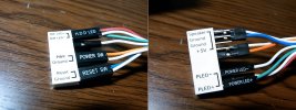
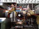
I got into the case again yesterday, and after manipulating some cables out of the way I was able to get access to the front panel connection pins. The long plug I had referred to earlier is something Asus calls a "Q-Connector". It's an intermediate plug one can plug all the smaller plugs into first, and then attach the intermediate plug to the MB completing all connections simultaneously.

First I just pulled the Switch Power from the Q-Connector and shorted those two pins. Then I also pulled the entire Q-Connector off and shorted the appropriate pins on the MB itself. Absolutely no sign of life.

The MB has an "SB_PWR Led" on the board, and when the PSU switch is turned on it flashes a green light approximately twice per second. The user manual only describes this Led as being either in an ON or OFF state. I found other Asus MB "blink rate" troubleshooting articles online, but they describe 3 different blink rates that don't come close to matching what this ASUS M2N32-SLI DELUXE board is doing.

All the hardware on the MB looks good. I don't see any blown cap's or any other sign of something obviously wrong. Even though the front panel power button is flaky and gets stuck in at times, I think I've eliminated it as the main problem with not starting. Since none of the fans are kicking to life, that suggests there's no 12V being supplied, and since I don't hear any system beeps I don't think the BIOS is even beginning to do POST.

So from here, how do I test if I have a broken PSU, or a broken MB?
 

Attachments

  • ASUS Q-Connector.jpg
    ASUS Q-Connector.jpg
    115.4 KB · Views: 4
So from here, how do I test if I have a broken PSU, or a broken MB?

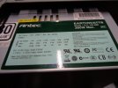
My bad for even asking that Q b4 looking it up. I did the "paper clip" test on the 24 pin plug, and the PSU fan did start up. Then I wanted to test voltages further with my multi-meter, and read 5 different articles on that process.... the authors contradicted each other and / or didn't give the specifics on the information I really wanted.

Only one article hinted that the "paper clip" jumper needs to stay in place, but didn't come out and say it. None of the articles made mention of whether or not the PSU should be plugged in and turned on. (I assume this is required, but I'd prefer "experts" put it in bold writing.)

One article said it would be safe to unplug the power supply from all the drives b4 proceeding. Another article agreed and added that expansion cards should also be removed! The other 3 "experts" made no mention of this detail at all.
 
Hi ImWolf - it's funny way to start a new year, but at least it isn't boring :)

Sorry, today I have a pretty thick schedule thus I won't be of much help, but let's give it a try anyway.

I assume that for "paper clip test" you mean shortcircuiting pins 15 and 16 on the motherboard power connector (see below).
That's actually the most direct test to see if the PSU works as it should ( I didn't mention it yet because it entails digging pretty deep in the wire jungle). Of course it doesn't tell you that all the voltages are OK, but if it brings the computer to life while the test on the Q-connector failed, then the motherboard is most likely the culprit - from outside dead chips look exactly like healthy ones.

Yes, the paper clip needs to stay in place all the time: the PSU has no memory, thus it's up to the motherboard to keep it on until the PC is turned off.

Authors often contradict each other, in particular when they pontificate by hearsay without having any direct experience of what they're talking about.
How much stuff you should disconnect before playing around with the PSU is a matter of prudence and common sense: all of it would give you maximum safety and plenty of scratched fingers, nothing at all might be somewhat risky but not really much. Still it's wise to pull the power plug (or to switch off the PSU) before disconnecting or reconnecting the power connector to the motherboard, lest some voltages reach the circuitry before other balancing ones thus wreaking havoc here and there.

That's all for now: a fidgeting wife is persistently nagging me that we're running late... see you tomorrow :)

1735807452444.png
 
Thanks for confirming things for me Chiron. Yes, I shorted the 15-16 pins and saw the PSU fan spinning, which is all the testing I've done so far. Now that I've watched a couple of videos (and with your input) I'm confident I won't have trouble testing the voltages on the 24 pin plug.

I also want to test the 4 pin ATX power plug, but I'm not finding specifics on that process. I assume that I would leave the jumper in place on the 24 pin plug, and then touch the multi-meter probes to the Ground and 12V leads on the 4 pin plug. In other words, I should not use a Ground on the 24 pin plug to test 12V on the 4 pin plug?
 
After testing all the 24 pin and 4 pin plugs off the PSU, my multi-meter says the PSU is delivering correct voltage at every connection. Can I now assume that the MB is officially dead, or is there something I missed?
 
Me voilà, back from a meeting of old fellow inmates of a notorious research asylum... er, lunatic institute... well, whatever. Great evening. Tolerable hangover. 3 cups of strong coffee to bring me back to life.

For all I know a motherboard has one single reference ground, thus it doesn't matter against which ground you measure your voltages - as long as all connectors are plugged in. If you want to measure the voltage on a floating connector it's another story though: then you'll better use its own ground for there's no guarantee that the PSU has a common ground for all the voltages it delivers.

"Dead" is a loaded word for a motherboard: the source of the malfunction might well be a single chip reasonably easy to replace, or even the CMOS battery gone flat over the years - it's just a plain non-rechargeable battery, you know. Frankly I've no idea how the power switch signal is processed but if it were through an IC powered from that battery, just replacing it might do the trick.

Good luck, and keep me posted!
 
it doesn't matter against which ground you measure your voltages - as long as all connectors are plugged in. If you want to measure the voltage on a floating connector it's another story though: then you'll better use its own ground for there's no guarantee that the PSU has a common ground for all the voltages it delivers.
I don't know how to check the voltages on a connector while it's plugged in.
CMOS battery gone flat over the years - it's just a plain non-rechargeable battery, you know.
From past experience of those CR2032 batteries going dead, this has only caused the stored BIOS data to be replaced by factory defaults. The machines would still spin fans, go through POST, and then deliver an error like "System not found", or something similar.
Frankly I've no idea how the power switch signal is processed but if it were through an IC powered from that battery, just replacing it might do the trick.
Maybe Asus had a "better idea" and starting the damn thing actually depends on the watch battery? It's conveniently located under 2 or 3 of the HDD's.
 
I don't know how to check the voltages on a connector while it's plugged in.
In the same way as you did the paper clip test: just insert a (straightened) paper clip from top alongside the wire as far as it goes, then measure there.
From past experience of those CR2032 batteries going dead, this has only caused the stored BIOS data to be replaced by factory defaults. The machines would still spin fans, go through POST, and then deliver an error like "System not found", or something similar.
Not all the motherboards are created equal...
Maybe Asus had a "better idea" and starting the damn thing actually depends on the watch battery? It's conveniently located under 2 or 3 of the HDD's.
Sounds familiar to me, it must be Murphy's law applied to motherboards :(
I mentioned it just as a possibility: were the battery easily accessible it might be worth a try, but if you have to take apart the whole bloody can to get there, then better forget it, pronounce the motherboard officially deceased and bury it in the nearest junkyard. Such a pity though...
 
Yes it would be a pity.... I just looked up what these 2006 used MB's are going for on EvilBay. WOW!!!

Since I might end up pulling the HDD's anyway, I think I'll do that and replace the battery just cuz.
 
In the same way as you did the paper clip test: just insert a (straightened) paper clip from top alongside the wire as far as it goes, then measure there.
I'm not seeing what you're describing here. Run a connection between the individual plug hole and the corresponding pin on the MB socket? Then check the voltage along that connecting wire?
 
Since I didn't have anything else pressing, I yanked one of the HDD's and the Graphics card which allowed me to replace the CR2032 battery. Didn't make a difference. Old battery tested at 2.92V while new one was at 3.3V.

After replacing this battery I again tried shorting the Power Switch jumper pins on the Front Panel pin-out.... no joy.

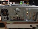
Along the way I noticed something I should have made note of already, there is nothing connected to the 4 pins for "chassis mounted warning speaker". This cheapo nightmare knuckle buster case didn't even include a speaker. Who ever designed this case was obviously a 1st degree white belt idiot who surely never had to actually install components in his monstrosity! I've already run out of foul language just dealing with what should be the most simple diagnostic procedures.

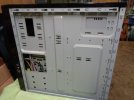
Anyway, I did take some poor quality photo's as well.....
 

Attachments

  • DSC00569.JPG
    DSC00569.JPG
    162.9 KB · Views: 8
  • DSC00562.JPG
    DSC00562.JPG
    161.4 KB · Views: 10
  • DSC00563.JPG
    DSC00563.JPG
    162.5 KB · Views: 9
  • DSC00565.JPG
    DSC00565.JPG
    157.8 KB · Views: 9
  • DSC00566.JPG
    DSC00566.JPG
    162.7 KB · Views: 9
I'm not seeing what you're describing here. Run a connection between the individual plug hole and the corresponding pin on the MB socket? Then check the voltage along that connecting wire?
No, sorry, I wasn't clear enough. There are at least two practical ways to measure voltages on a plugged-in connector without removing it, both working on the wires side:
The first one is to pierce the wire insulator with a needle until you reach the copper and then use it as a contact - but two times out of three the first thing you manage to pierce is your finger.
The second one is to stick something metallic (e.g. a straightened paper clip) from the top into the connector hole along the insulated wire and push it in until you touch metal (the actual contact). Easier done then said, and most of the times it works.
 
Back
Top